ILS Basics
NDB and VOR approaches, with their lateral guidance to the runway, greatly improve the reliability of flight schedules. But without the capability to provide vertical guidance to the runway they are limited in utility. No vertical guidance classes them as non-precision approaches.
The Instrument Landing System adds glide-slope, or elevation information. Commonly called the ILS, it is the mother of them all when it comes to getting down close to the ground. In every sense it is a precision approach system and with modern equipment it can guide you right down to the runway—zero Decision-Height and zero visibility.
The ILS Components
When you fly the ILS, you're following the co-location of two signals: a localizer for lateral guidance (VHF); and a glide slope for vertical guidance (UHF). When you tune your Nav. receiver to a localizer frequency a second receiver, the glide-slope receiver, is automatically tuned to its proper frequency. The pairing is automatic.

There's more to an ILS than the localizer and glide slope signals. The FAA categorizes the components this way:
- Guidance information: the localizer and glide slope.
- Range information: the outer marker (OM) and the middle marker (MM) beacons.
- Visual information: approach lights, touchdown and centerline lights, runway lights.
Descriptions of the ILS components

Three-dimensional depiction of the Instrument Landing System. Early VOR indicators had the yellow and blue-colored arc as shown here, but it was later phased out because it provided no useful information. Localizer antennas shown at far end of runway.
The Localizer
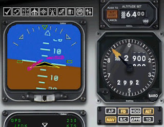
The localizer signal provides azimuth, or lateral, information to guide the aircraft to the centerline of the runway. It is similar to a VOR signal except that it provides radial information for only a single course; the runway heading. Localizer information is displayed on the same indicator as your VOR information.
When tracking the localizer the pilot turns towards the needle in the same manner as with VOR navigation.
 The localizer consists of only a single course.
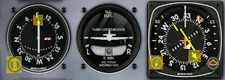
The localizer course needle is sensitive as a VOR needle. Heading adjustments four times as must be much sensitivity of the indicator. For VOR work, each smaller because of the increased dot under the needle represents 2° deviation from course while for the localizer each dot under the needle represents 0.5° deviation from course.
Because the localizer provides information for only one radial, the runway heading, the Nav. receiver automatically cuts out the OBS, the Omni Bearing Selector knob. Rotating the OBS still rotates the course ring on the instrument, but has no affect on the needle. How sensitive is the Localizer? Near the Outer Marker, a one-dot deviation puts you about 500 ft. from the centerline. Near the Middle Marker, one dot means you're off course by 150 ft.
How sensitive is the Localizer? Near the Outer Marker, a one-dot deviation puts you about 500 ft. from the centerline. Near the Middle Marker, one dot means you're off course by 150 ft.
Specifics of the Localizer
The localizer antenna is located at the far end of the runway.
The approach course of the localizer is called the front course.
The course line in the opposite direction to the front course is called the back course.
The localizer signal is normally usable 18 NM from the field.
The Morse code Identification of the localizer consists of a three-letter identifier preceded by the letter I. Here is the localizer identifier for Providence's Runway 5R.
The Glide Slope
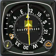
The Glide Slope is the signal that provides vertical guidance to the aircraft during the ILS approach. The standard glide-slope path is 3° downhill to the end of the runway. Follow it faithfully and your altitude will be precisely correct when you reach the touchdown zone of the runway.
Tracking the glide slope is identical to tracking a localizer. If the glide-slope needle swings away from center—up or down—maneuver the aircraft towards the needle by adjusting the engine's power. Don't point the aircraft's nose up or down.

The glide path projection angle is normally adjusted to 3 degrees above horizontal so that it intersects the MM at about 200 feet and the OM at about 1,400 feet above the runway elevation. The glide slope is normally usable to a distance of 10 NM.
Marker Beacons
Marker beacons are used to alert the pilot that an action (e.g., altitude check) is needed. This information is presented to the pilot by audio and visual cues. The ILS may contain three marker beacons: inner, middle and outer. The inner marker is used only for Category II operations. The marker beacons are located at specified intervals along the ILS approach and are identified by discrete audio and visual characteristics (see the table below). All marker beacons operate on a frequency of 75 MHz.
Indications | MARKER | CODE | LIGHT | SOUND |
| OM | _ _ _ | BLUE | 400 Hz
two dashes/second |
| MM | ._._._ | AMBER | 1300 Hz
Alternate dot and dash |
| IM | . . | WHITE | 3000 Hz |
| BC | . . | WHITE |
Notice above that the sound gets "quicker" and the tone "higher" as the aircraft moves towards the airport—first dashes, then dots and dashes, finally just dots.
The OM, 4 to 7 NM from the runway threshold, normally indicates where an aircraft intercepts the glide path when at the published altitude
The MM, 3500 feet from the runway threshold, is the Decision Height point for a normal ILS approach. On glide path at the MM an aircraft will be approximately 200 feet above the runway.
The IM. 1000 feet from the runway threshold, is the Decision Height point for a Category II approach. See later for description of categories of ILS approaches.
BC ... Most, but not all, airports with an ILS also offer guidance on the back course. The BC marker identifies the FAF for the back course. A Back-Course approach is non-precision since there is no glide path associated with it.
The majority of problems in locating marker beacons are the availability of real estate and access to utilities.
Decision Height?
The ILS brings in a brand new term, Decision Height, or DH as you will always hear it from here on. Thus far, the altitude published in the minimums section of the approach plates that you have used has been the MDA, or Minimum Descent Altitude. When flying a non-precision approach, you are not authorized to descend below the MDA unless you can see the runway and make a normal landing.
DH has a similar meaning. The DH for an ILS approach is a point on the glide slopedetermined by the altimeterwhere a decision must be made to either continue the landing or execute a missed approach. That's pretty simple.
Consider the minimums, below, for Runway 5R at Green airport in Providence, R.I.
Approach minimums | CATEGORY | A | B | C | D |
| S-ILS 5R | 253/18 |
| S-LOC 5R | 720/24 | 720/60 | 720 - 1½ |
| CIRCLING | 720 - 1 | 720 - 1¾ | 720 - 2 |
Note: For this example, the military minimums data has been omitted.
Here is the interpretation of the minimums data from the table above, for any Category A or B aircraft, i.e., 1.3 × Stall Speed equals or is less than 120 kts.
The minimums for a straight-in ILS approach to runway 5R are 253 ft. DH and 1800 ft. RVR. As you descend down the glide slope, when your altimeter reads 253 ft., you must make a decision whether to continue the descent and approach, or to execute a missed approach.
If the Glide Slope is unavailable for whatever reason, one could fly a Localizer approach straight in to Runway 5R. In that case, with no glide slope, the approach is no longer a precision approach because no vertical guidance information is being provided. The 720 ft. on the chart is now the MDA, not the DH, and the minimum RVR has increased to 2400 ft. Here, like the VOR and NDB approaches that you have already flown, you may descend to the MDA as soon as you pass the FAF.
The circling approach, of course, is also a non-precision approach. Its MDA is 720 ft and the minimum visibility is one mile. Notice that RVR is not used here. RVR is strictly for visibility down a runway. In a circling approach, the pilot's concern is his or her ability to keep the airport in sight while maneuvering for a runway which differs from the approach course
Many airline carriers require Category D minimums for a circling approach even if the aircraft falls in the Category A or B range. The circling approach is difficult and raising the minimums relieves some of the stress.
Sad to say that there are air carrier pilots who refuse to accept anything other than an ILS approach due to their lack of experience with the other procedures. They would prefer to encounter a runway with unfavorable winds. Nor do they trust their "black boxes" without any experience with them on alternate approaches.
ILS Categories
For the longest time, the minimums for an ILS approach were one-half mile visibility and a 200 ft. ceiling. Then things began to change, principally the reliability, accuracy, and capability of the autopilot. RVR, a more reliable measurement of visibility, began to appear on approach plates, too.
As these changes evolved, the FAA designated three categories of ILS approaches, with successively lower minimums. Later, they decided that three categories didn't fit all of the desired situations and further expanded it. The next table shows the full range of ILS approaches.
>
Categories | Category | DH | RVR | Remarks |
| I | 2400 feet |
| I | 200 feet | 1800 feet | With touchdown zone and runway centerline lighting . |
| 100 feet | Half the minimums of a standard Cat I approach |
| face="Verdana">IIIa | below 100 feet | 700 feet |
| IIIb | below 50 feet | less than 700 feet but not less than 150 feet |
| IIIc | No DH | No RVR limitation |
Data from Aeronautical Information Manual,AIM.
NOTE: Cat. IIIc approach is a zero-zero approach.
The autopilot is in full control of the aircraft for any approach below Cat. I. And you can't initiate a Cat. II or Cat. III approach at just any airport simply because the weather minimums require it. Those approaches, like all the others, must be approved and published.
Straight-in approach minimums for Runway 5R,
Green airport, Providence, R.I. Field elevation is 55 ft. | Type Approach | DH/MDA ft. | RVR ft. |
| NDB | 740 | 4000 |
| VOR | 720 |
| LOC | 720 | 2400 |
| ILS | 1800* |
| ILS | 153 |
* Touchdown zone identification lights and runway centerline lights are available.
The "LOC" approach is a Localizer approach which utilizes only the localizer component of an ILS. It is thus a non-precision approach with higher minimums. Localizer approaches are the first subject covered in the next chapter.
Compass Locators
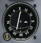
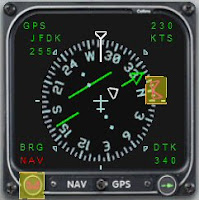
 | Airline captains use RMI's more frequently than you think, even if seldom for an NDB approach.
It has become increasingly common to collocate a compass locator transmitter with the Outer Marker beacon. Some airports also have them with the Middle Marker and Inner Marker beacons, too. These LF NDBs serve the dual function of keeping pilots appraised of their position relative to the marker beacons and also can be navigation aids in their own right. |
Compass-locator NDBs usually have a power of less than 25 watts, with a range of at least 15 miles and operate between 190 and 535 KHz. At some locations, higher powered radio beacons, up to 400 watts, are used as OM compass locators. These generally carry Transcribed Weather Broadcast information (TWEB).
Compass locators transmit two-letter identification groups. The outer locator transmits the first two letters of the localizer ident Morse code, and the middle locator transmits the last two letters of the localizer ident code. In both cases, the ident begins with the letter "I." For example, at Providence, Runway 5R:
Localizer Ident: I-PVD
OM Ident: I-PV
MM Ident: I-VD
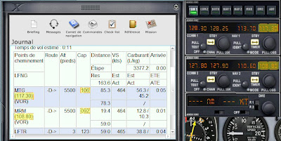
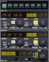
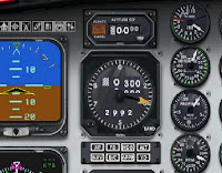
 | Across the top is distance in NM (5.1), ground speed in kts (80) and the time to station in minutes (4). This model lets you select which VOR the DME is measuring distance from—the one tuned with Nav receiver #1 (N1) as in this case, or Nav receiver #2 (N2). |
The DME is slant range, not distance along the ground. The aircraft is in the air and the distance measured is from up there to the station. So you'll always be somewhat closer to the station than indicated by the DME.
The error is greater for short distances than large distances. For example, if you were cruising at 5000 ft. and the DME indicated 5.1 NM as in the illustration, your ground distance to the station is about 4.9 NM, a 3% error. If your DME reports 30 miles, still at 5000 ft, ground distance now is 70 ft shorter than the slant range, an insignificant error.
Distance Measuring Equipment can be a crucial part of an ILS installation. Not only does it assist with the approach, but it can be a necessary component to guide you to the FAF to begin the approach. You'll get a chance to do some DME work in the final section of the ILS approaches.
Functions of the DME in an approach:
- When installed with the ILS and specified in the approach procedure, DME may be used:
- In lieu of the OM,
- As a back course (BC) final approach fix (FAF), and
- To establish other fixes on the localizer course.
- In some cases, DME from a separate facility may be used:
- To provide initial approach segments,
- As a FAF for BC approaches, and
- As a substitute for the OM.


 .
. 


